Passive Components
The components which doesn’t have any internal capacity to change energy format from one form to another.
Resistor : Resistors are the most commonly used component in electronics and their purpose is to create specified values of current and voltage in a circuit.This is used in electrical circuits to maintain a constant relation between current flow and voltage. The unit for measuring resistance is the OHM. The current through a resistor is in direct proportion to the voltage across the resistor's terminals. This relationship is represented by Ohm's law:
I = Current measured in Amps
V = Voltage measured in Volts
R = Resistance measured in Ohms
Resistors provide a specific amount of resistance to a path in a circuit or wire. Ohm's law is used to calculate the properties related to resistance.
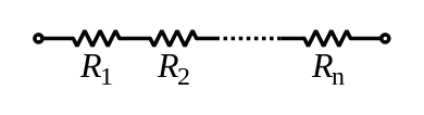
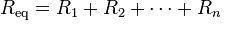
Series Resistor
In a series configuration, the current through all of the resistors is the same, but the voltage across each resistor will be in proportion to its resistance. The potential difference (voltage) seen across the network is the sum of those voltages, thus the total resistance can be found as the sum of those resistances:
The components which doesn’t have any internal capacity to change energy format from one form to another.
Resistor : Resistors are the most commonly used component in electronics and their purpose is to create specified values of current and voltage in a circuit.This is used in electrical circuits to maintain a constant relation between current flow and voltage. The unit for measuring resistance is the OHM. The current through a resistor is in direct proportion to the voltage across the resistor's terminals. This relationship is represented by Ohm's law:
I = Current measured in Amps
V = Voltage measured in Volts
R = Resistance measured in Ohms
Resistors provide a specific amount of resistance to a path in a circuit or wire. Ohm's law is used to calculate the properties related to resistance.
Series Resistor
In a series configuration, the current through all of the resistors is the same, but the voltage across each resistor will be in proportion to its resistance. The potential difference (voltage) seen across the network is the sum of those voltages, thus the total resistance can be found as the sum of those resistances:
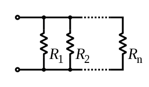
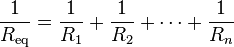
Parallel Resistor
Resistors in a parallel configuration are each subject to the same potential difference (voltage), however the currents through them add. The conductances of the resistors then add to determine the conductance of the network. Thus the equivalent resistance (Req) of the network can be computed:
Resistors in a parallel configuration are each subject to the same potential difference (voltage), however the currents through them add. The conductances of the resistors then add to determine the conductance of the network. Thus the equivalent resistance (Req) of the network can be computed:
Types of Resistors
Capacitor: A device that stores energy in electric field.
Types of polarized capacitor:
Inductors:
A static device which transfer the electrical energy from primary winding ,works on the principle of mutual induction.Transformer allows only AC current.
Vs = Ns
Vp Np
Vs is induced voltage in secondary winding
Vp is induced voltage in primary winding
Ns is number of turns in secondary winding
Np is number of turns in primary winding
Basic Types of Transformer
- Fixed Resistor: The Fixed resistance are those whose values cannot be changed.
- Variable Resistor: Value of the resistance that can be changed within specific range.
Capacitor: A device that stores energy in electric field.
- Two conductive plate separated by a non conductive material.
- Electrons accumulate on one plate forcing electrons away from the other plate leaving a net positive charge.
- Capacitor is very small and temporary storage battery.
- Capacitor blocks the passage of DC current.
- Capacitor passes AC current.
- Unit of capacitance is Faraday’s.
- Value of capacitance is given by its value and the max voltage which can be safely applied to it which is known as working voltage.
Types of polarized capacitor:
- Electrolytic capacitor
- Tantalum capacitor
- Can capacitor
Inductors:
- Inductor is a coil of wire through which electrons move and energy is stored in the resulting magnetic field.
- It stores energy in magnetic field not in electric field.
- When the source of electron is removed,the magnetic field collapses immediately.
- Inductance is measured in Henry.
- Air core inductors also include the radio frequency inductors.
- The ferromagnetic core inductors include laminated core, ferrite-core and toroidal core inductors.
- The final category is the variable inductor.
- Resonant Circuits
- Electric Transmission
- Filter in power supply
- Energy storage devices in SMPS.
- Audio frequencies.
A static device which transfer the electrical energy from primary winding ,works on the principle of mutual induction.Transformer allows only AC current.
Vs = Ns
Vp Np
Vs is induced voltage in secondary winding
Vp is induced voltage in primary winding
Ns is number of turns in secondary winding
Np is number of turns in primary winding
Basic Types of Transformer
- Step-down: When secondary winding will be less than primary winding
- Step-up: When secondary winding will be more than primary winding.
